Loads/Analysis Tab

Load Combinations
The following default load combinations are automatically created by CIP RC/PT Girder
You can specify which allowable stresses should be used for estimating the minimum PJack, f'ci, and f'c. Allowable stresses can be defined under Design Parameters.
The following Combination Types are offered:
The Loads/Analysis tab is used to add both loads and combinations to the bridge. The tab consists of three panes or views to facilitate the creation and loads and the formation of combinations. The left-side view is referred to as the "Combination Tree" and contains the list of user-defined combinations. The right-side view is referred to as the "Load Tree" and actually contains two lists of loads: Library Live Loads obtained from the Live Load Library and user-defined project loads. The bottom view displays a graphical representation of the loads on the bridge.
The list of Library Live Loads in the Load Tree can only be viewed; they cannot be edited. To view a Library Live Load, double-click or select it using the right mouse button and then select View Library Live Load. The Library Live Loads are intended to be placed into combinations or into the project loads by selecting them with the left mouse button and then dragging them to the appropriate combination or into the project loads. Library Live Loads may be edited once they are in the list of project loads.
Combinations are added by right-clicking in the Combination view and selecting Add Combination. Combinations contain references to loads on the bridge. You may create loadings on the bridge by right-clicking on load categories on either the project load tree or the combination tree. Adding loads by right-clicking on the combination tree performs two activities: first, a loading is created on the bridge and second, a reference to it is added to the combination. You may add combination items to a combination by dragging loads, either from the list of library live loads or from the list of project loads currently defined for the bridge to a particular combination.
Deleting a combination item from a combination merely removes the reference to the loading from the combination; the actual loading is still on the bridge. Deleting a loading from the list of project loads removes all references to it for all combinations and then deletes it from the bridge.
Loads and combinations are added to the bridge in the context of an Analysis Case, i.e., Initial and Final. Adding a combination to the Initial case will result in a combination of responses at the Initial case. Loadings function in a similar fashion: adding a live load to the Final case will only put the live load on the bridge for the final case and will only be available for combinations in the Final case. Dead loads work a little differently since they are permanent type loads: adding a dead load in the Final case will direct CIP RC/PT Girder to apply the loading in the Final case and it also will be available for combination in the Initial and Final cases. It will not be available in the Initial case.
After defining loads and/or combinations, you can perform an analysis of the structure by clicking the Run Analysis button, by clicking the appropriate icon ( ) in the Toolbar, or by selecting the Run Analysis command from the View menu. After performing the analysis, the default analysis result text report displays in the Analysis Results screen. Design-related analysis results, such as stress and flexure checks, can be viewed in the Design Results screen. You can perform an analysis on either a model created using the full cross section or for an individual girder. To specify the model to generate, select the appropriate girder from the Girder drop-down list.
If you selected the Full Width Only option on the Project tab, then only the full bridge analysis will be available. If you selected the Optional Girder Analysis option, then the individual girders as well as the full cross section will be available.
Specifying Dead Load and Superimposed Dead Load
CIP RC/PT Girder allows you to add point and trapezoidal loadings to the project loads and to a combination and classify them as either a Dead Load (DC) or a Superimposed Dead Load (DW). Intrinsic self-weight is included as a Dead Load by selecting the Include Self Weight option located in the Dead Loads dialog box. To view, add, or modify dead and superimposed dead loads, select the analysis/design case from the drop-down list and then either double-click the name of the Dead or Superimposed Load or right-click Dead Load/DC Group or Superimposed Dead Load/DW Group select the Add Load command.
Specifying Uniform Temperature Load
- Select the analysis/design case from the drop-down list.
- Right-click the Temperature Load Group and select the Add Uniform Temperature command.
- When the Uniform Temperature Load dialog box opens, enter the Load Name, as well as the Rise and Fall fields. Note that Rise or Fall are only the loading names and a drop in temperature (i.e., Fall) should be entered as a negative value. These values will be applied uniformly to the entire superstructure. Click the OK button to return to the Loads/Analysis tab.
- Double-click the name of the uniform load to view or edit the load.
Nomenclature
| Setting | Description |
|---|---|
| Fall | The uniform temperature fall value. |
| Load Name | The unique ID for the temperature load. |
| Rise | The uniform temperature rise value. |
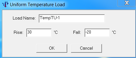
CIP RC/PT Girder allows you to add a Uniform (TU) Temperature Load to the project loads and to combinations. Select the analysis/design case from the drop-down list, right-click the Temperature Load Group and select the Add Uniform Temperature command to open the Uniform Temperature Load dialog box.
Specifying Gradient Temperature Load
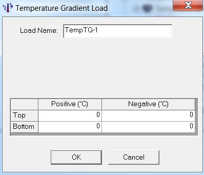
CIP RC/PT Girder allows you to add a Gradient (TG) Temperature Load to the project loads and to combinations. Gradient temperature allows you to change the temperature of the top and bottom independently (e.g., +10, +5, and -30, -20). Gradient temperature loadings produce a constant strain plus curvature. Perform the following steps to add a gradient temperature load:
- Select the analysis/design case from the drop-down list.
- Right-click the Temperature Load Group and select the Add Gradient Temperature command.
- When the Temperature Gradient Load dialog box opens, enter the Load Name and select one of the AASHTO Specification-defined zones or select User-defined and enter the rise and fall values (in degrees) for the top and bottom of the superstructure. Click the OK button to return to the Loads/Analysis tab.
- Double-click the name of the gradient load to view or edit the load.
Nomenclature
| Setting | Description |
|---|---|
| Load Name | The unique ID for the temperature load. |
| Negative/Bottom | The temperature fall value at the bottom of the member. |
| Negative/Top | The temperature fall value at the top of the member. |
| Positive/Bottom | The temperature rise value at the bottom of the member. |
| Positive/Top | The temperature rise value at the top of the member. |
Specifying Live Load
CIP RC/PT Girder only allows one live load to be added to the project at a time. The Locked Library Loads includes the following CHBDC live load groups. These groups of loads follow the provisions of CHBDC with respect to the number of design lanes, the combinations of vehicles, impact factor, and the live load reduction due to the presence of multiple lanes.

Defining Pedestrian Load
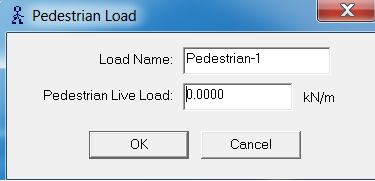
CIP RC/PT Girder allows you to add a Pedestrian Load to the project loads and to combinations as long as a Live Load is present. Perform the following steps to add a pedestrian load:
- Select the analysis/design case from the drop-down list.
- Right-click the Pedestrian Load Group and select the Add Pedestrian Load command.
- When the Pedestrian Load dialog box opens, enter the value of the load and click the OK button to return to the Loads/Analysis tab.
- Double-click the name of the pedestrian load to view or edit the load.
Nomenclature
| Setting | Description |
|---|---|
| Load Name | The unique ID for the pedestrian load. |
| Pedestrian Live Load | The value of the pedestrian live load. |
Live Load Distribution
For live loads, CIP RC/PT Girder employs the Simplified Method of Analysis specified in CHBDC 5.7.1.
Specifying Combination Factors
CIP RC/PT Girder uses specified loads and other factors in the formation of combinations. To view or change these factors, select the analysis/design case (e.g., Initial or Final) from the drop-down list and then either double-click the name of the combination (e.g., SLS Combination 1 - Final) or right-click the name of the combination and select the Edit Combination command
Running an Analysis
After defining project loads and combinations, you can perform an analysis of the structure by clicking the Run Analysis button, by clicking the appropriate icon ( ) in the Toolbar, or by selecting the Run Analysis command from the View menu. After performing the analysis, the default analysis result text report displays in the Analysis Results screen.
Technical Discussion
CIP RC/PT Girder checks and designs a box girder bridge using combinations and, therefore, it provides considerable flexibility to construct combinations and to include them in the analysis and design. CIP RC/PT Girder uses certain types of combinations (e.g., strength and service) to perform certain activities, such as the design of minimum Pjack and As-required. Therefore, it is important for you to know which type of combination to add to an analysis/design case to achieve your needs.
Analysis results due to any loading in any combination, in addition to combination results are available for review in the Analysis Results screen that opens after clicking the Run Analysis button. You can add a combination that includes loadings that you are interested in from an analysis standpoint but not necessarily from a design standpoint. CIP RC/PT Girder will use that combination in performing specification checks and design activities (depending on its type), but if you ignore that combination in making your design decision, then it won't influence the design. Or you can add loads to the project loads directly, independent of any combination and be able to obtain analysis results for those loads; the responses will not be part of any combination.
You may reference any desired loads in any combination using the Loads/Analysis tab. CIP RC/PT Girder will automatically add post-tensioning and shrinkage loads to all combinations before an analysis begins. The response due to shrinkage will be zero unless you use one of the time dependent loss options.
- Special Service-Type Combinations
- Combinations from Permanent Loadings
For each analysis case, a combination is generated containing permanent type loads. The names of the combinations are: , and . "Perm Loads_Init and Perm Loads_Final" .
- Dead Loads Initial (DC)
For the Initial analysis case,a combination is generated containing only component weight type loads. The name of this combination is "DL_Init."
- Post-tensioning Initial
For the Initial analysis case, a combination is generated containing only PT loads. The name of this combination is "PS_Init."
- Dead Loads Final (DC/DW)
For the Final analysis case,a combination is generated containing component weight (DC) and added dead loads (DW). The name of this combination is "DL_Final."
- Displacement Check Combinations
For every live load defined at any analysis case:
Responses for non-live loads, i.e., dead load, added dead load, temperature (TU/TG), post-tensioning and shrinkage are obtained directly through the structural analysis.
Nomenclature
| Term | Definition |
|---|---|
| Case | The load case for the analysis. |
| Combination Factors | Define the combination factors using the Combination Factors dialog box. |
| Dead Load/DC Group | Define the dead load using the Dead Loads dialog box. |
| Final | Includes losses but allows the structure to sway longitudinally (if this is consistent with the specified boundary conditions). (Analysis Case) |
| Initial and Final | Includes losses but constrains the structure from translating longitudinally. (Analysis Case) |
| Girder | The frame or girder to analyze. |
| Initial | Checks/designs the structure before losses. (Analysis Case) |
| Live Load Dist Factors | Modify the live load distribution factors using the Live Load Distribution Factors dialog box. |
| Live Load Group | Define the live load using the Live Load dialog box. |
| Pedestrian Load Group | Define the pedestrian load using the Pedestrian Load dialog box. |
| Run Analysis | Run the analysis based on the selected parameters and view the results in the Analysis Results screen. |
| Superimposed Dead Load/ DW Group: | Define the superimposed dead load using the Dead Loads dialog box. |
| Temperature Load Group | Define the either a uniform temperature load or a gradient temperature load. |